Integration examples
Connection with Autopilot 1x via CAN
No configuration is necessary for MEX, the configuration for communication with Autopilot 1x is set by default.
The configuration required in 1x PDI Builder to communicate with MEX via CAN is explained in the Integration Examples section of the 1x PDI Builder manual, click here to access it.
CAN Configuration
CAN Reception IDs
First of all, users can setup the receiving CAN Ids for each one of the three possible Veronte Autopilots 1x in the Arbitration menu.
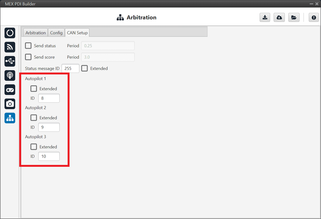
Arbitration - CAN Ids of autopilots
Note
If arbitration is not enabled, and therefore only a 1x autopilot is being used, no CAN Ids need to be configured here.
CAN I/O Interconnections
Once CAN IDs are set, users shall configure:
Input Filters to be used (as communication with MEX has to be always through a Filter).
The connection between input filters and data Consumers.
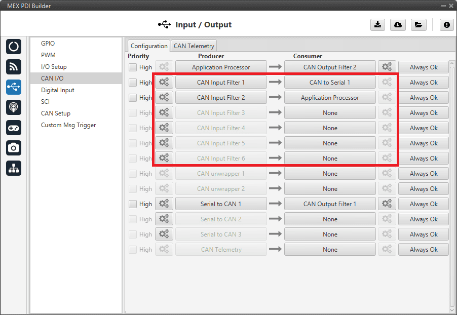
CAN I/O interconnections
For more information on CAN I/O configuration, see section CAN I/O of this manual.
Next step is to connect each of the desired data Producers to an Output Filter, and configure both the Producer and the Output Filter:
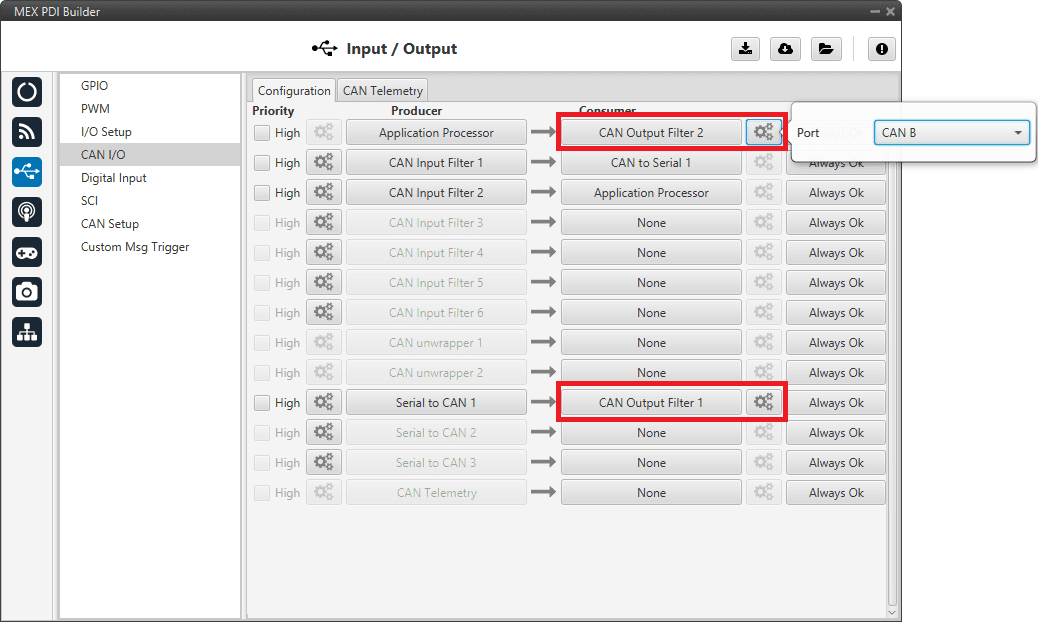
CAN Output Filters
CAN Telemetry
In addition, MEX can send telemetry via CAN.
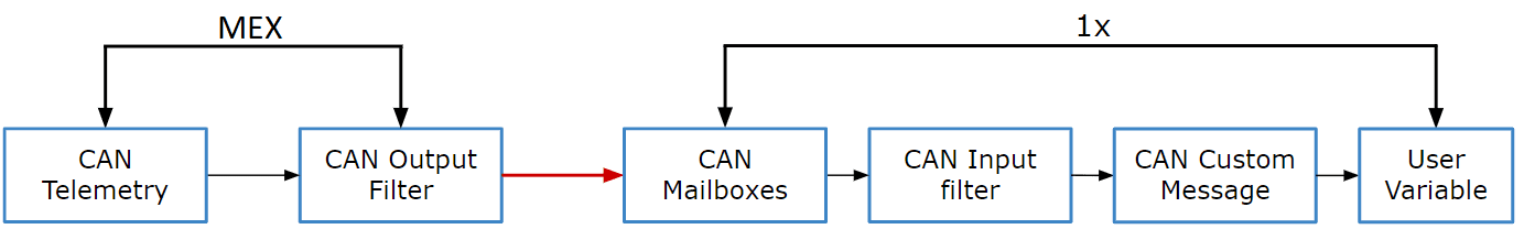
Communication diagram 1x-MEX
The user must follow the steps below to enable this function and to configure an Autopilot 1x to read its telemetry:
MEX PDI Builder side
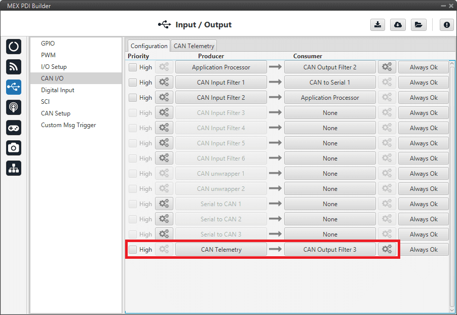
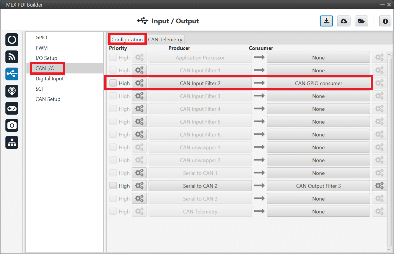
Go to Input/Output menu \(\Rightarrow\) CAN I/O section \(\Rightarrow\) Configuration tab.
Connect CAN Telemetry to a CAN Ouptut Filter as follows:
CAN I/O Custom Telemetry
Go to the CAN Telemetry tab.
Select the fields to send in the TX section, as it is a Producer. More information about the configuration of telemetry messages can be found in the CAN Telemetry section.

CAN Custom Telemetry
For example, a telemetry messsage with a variable set to ID 90:

CAN Custom Telemetry example
1x PDI Builder side
Go to UI menu \(\Rightarrow\) Variables section \(\Rightarrow\) Reals Vars tab.
Rename a User Variable, that will be used to store the value received from MEX:

1x PDI Builder - User Variable renamed
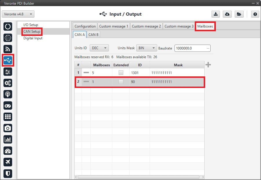
Go to Input/Output menu \(\Rightarrow\) CAN Setup section \(\Rightarrow\) Mailboxes tab.
Configure the mailbox to receive the message with ID 90 in 1x PDI Builder:
1x PDI Builder - Mailbox configuration
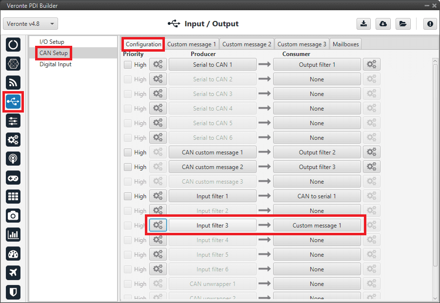
Go to Input/Output menu \(\Rightarrow\) CAN Setup section \(\Rightarrow\) Configuration tab.
Connect an Input filter with the right CAN ID to a Custom message consumer:
1x PDI Builder - Input filter
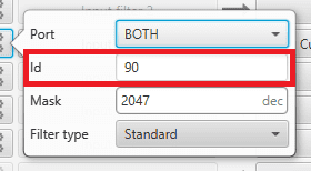
1x PDI Builder - Input filter configuration
Go to Input/Output menu \(\Rightarrow\) CAN Setup section \(\Rightarrow\) Custom message 1 tab (as Custom Message 1 has been selected as consumer).
Configure the reading of the message and store the received value in the user variable renamed above:
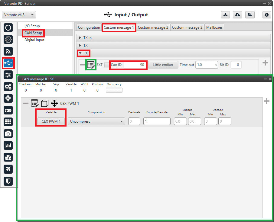
1x PDI Builder - Custom Message configuration
Commanding/Reading PWMs
The appropriate PWM message format is described in Command PWMs -> CAN Bus protocol section of the MEX Software manual.
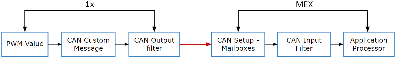
Communication diagram 1x-MEX
The following steps command PWM from Autopilot 1x to MEX:
1x PDI Builder side
Go to Input/Output menu \(\Rightarrow\) CAN Setup section \(\Rightarrow\) Configuration tab.
Connect a CAN custom message to an Output filter to send the message:

PWM Command - CAN Custom Message
Go to Input/Output menu \(\Rightarrow\) CAN Setup section \(\Rightarrow\) Custom Message 2 tab (because Custom Message 2 has been selected as consumer).
Build a CAN custom message using the PWM variable and the appropriate Message format. CAN ID is arbitrary, for this example we will use ID 100:
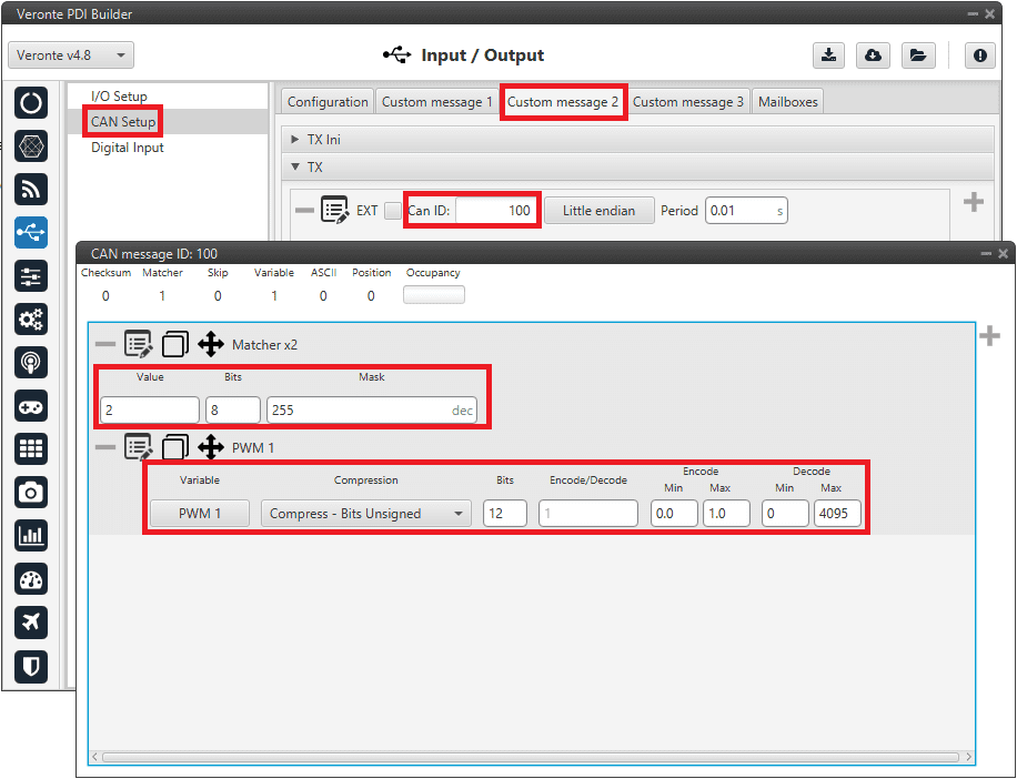
PWM Command - CAN Custom Message configuration
Message format:
Matcher (2) [8 bits]
PWM 1 [12 bits]
PWM 2 [12 bits]
PWM 3 [12 bits]
PWM 4 [12 bits]
Matcher (3) [8 bits]
PWM 5 [12 bits]
PWM 6 [12 bits]
PWM 7 [12 bits]
PWM 8 [12 bits]
Each PWM variable has to be set using the following format:
Variable: PWM X
Compression: Compress - Bits Unsigned
Bits: 12
Encode: Min=0.0 / Max=1.0
Decode: Min=0 / Max=4095
MEX PDI Builder side
Go to Input/Output menu \(\Rightarrow\) CAN Setup section.
Create the mailbox to receive the new message (ID 100):
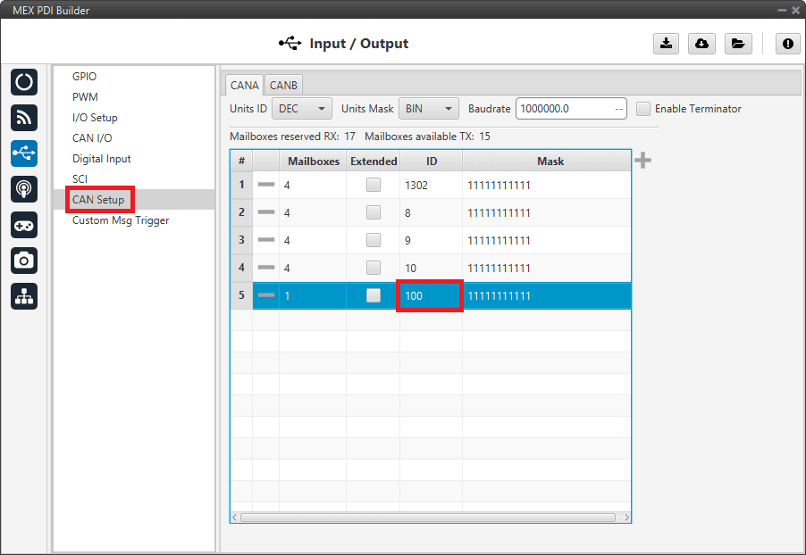
PWM Command- Mailbox configuration
Go to Input/Output menu \(\Rightarrow\) CAN I/O section \(\Rightarrow\) Configuration tab.
Connect an Input filter with the right CAN ID to the Application Processor consumer:
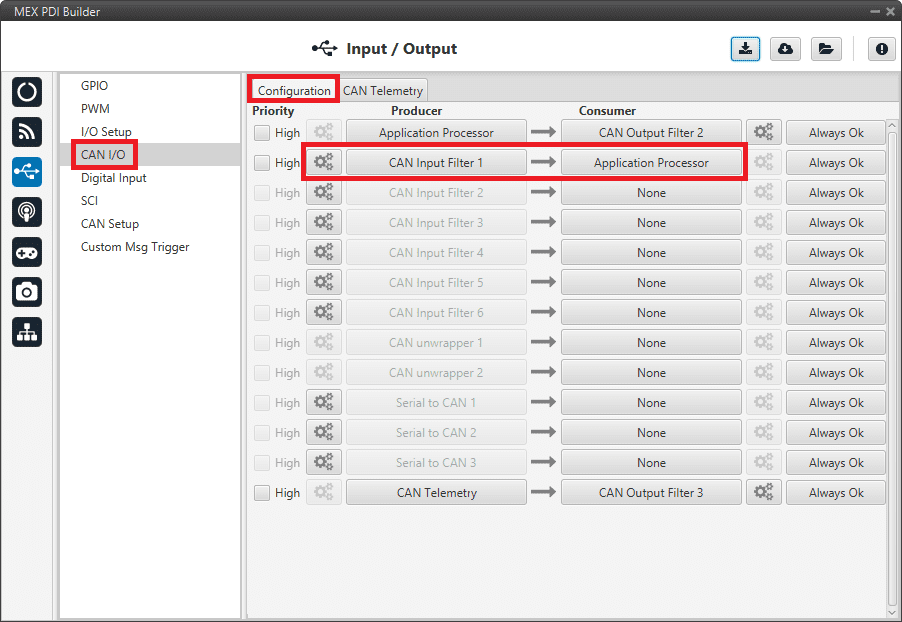
PWM Command - Input filter
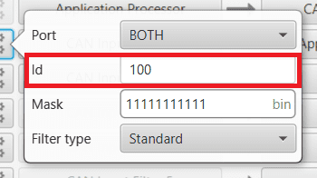
PWM Command - Input filter configuration
Go to Input/Output menu \(\Rightarrow\) PWM section \(\Rightarrow\) PWM 1 tab (as PWM 1 has been selected in 1x PDI Builder).
Configure parameters for PWM 1:

PWM Command - PWM configuration
Go to Input/Output menu \(\Rightarrow\) GPIO section.
Check that this PWM pin (PWM 1 in this case) has correctly switched from GPIO to PWM.
It should look like this:
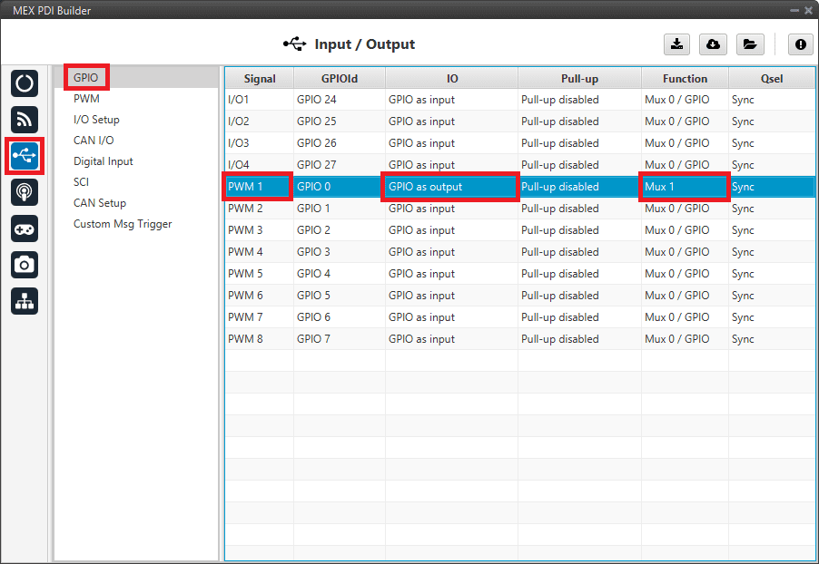
PWM Command - GPIO configuration
IO: GPIO as output.
Function: Mux 1.
Finally, export the configuration and save changes.
GPIO Command
The following are the steps to send a GPIO command from the Veronte Autopilot 1x, receive it at MEX and process it, so that MEX carries out the command.
GPIO Command is very similar to PWM command with a few differences.
1x PDI Builder side
Go to Input/Output menu \(\Rightarrow\) CAN Setup section \(\Rightarrow\) Configuration tab.
Connect, as Producer, a ‘CAN GPIO remote’ to an Output filter:

GPIO Command - 1x CAN Setup
CAN GPIO remote must be configured. For more information about its configuration, read CAN Setup section of 1x PDI Builder user manual.
GPIO Command - 1x CAN Setup configuration
Go to Automations menu.
GPIO must be activated using an ‘Output action’:

GPIO Command - 1x Automation configuration
MEX PDI Builder side
Jetibox
MEX is able to simulate a Jetibox to read telemetry from Legacy Jeti devices, the following steps need to be taken:
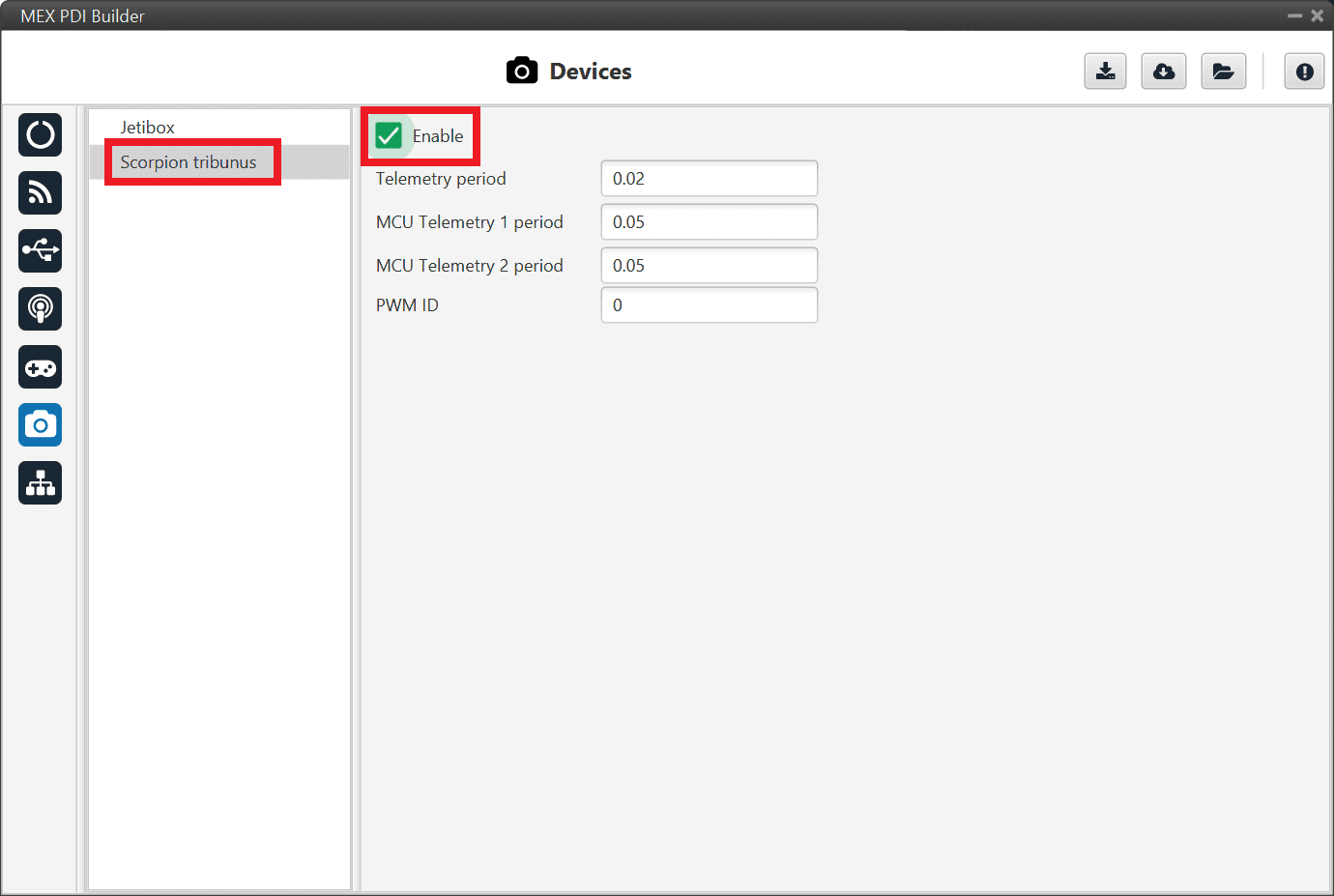
Go to Devices menu \(\Rightarrow\) Jetibox section.
Enable it and select a SCI Port, in this example SCI A is selected:
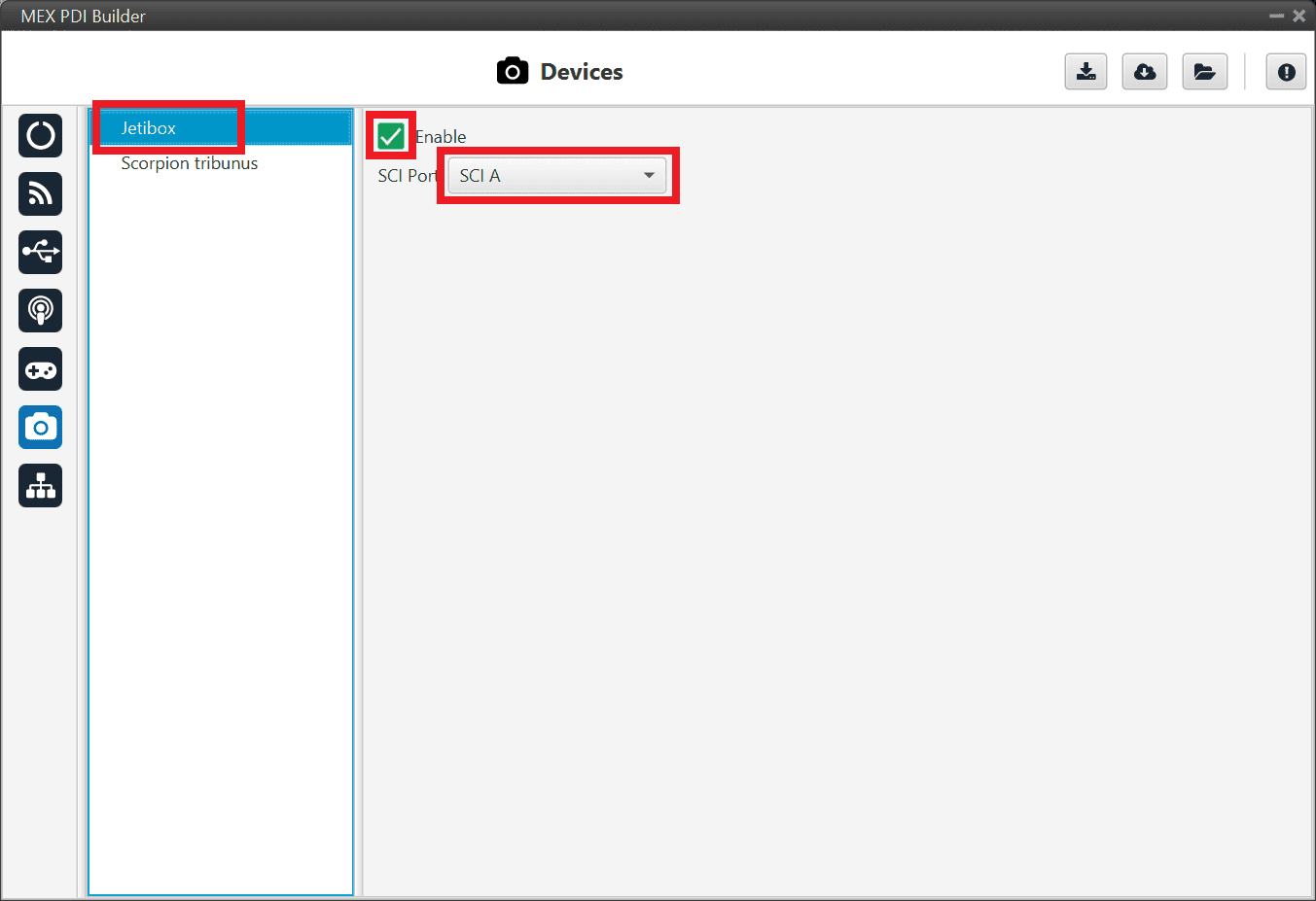
Jeti box Devices configuration
Go to Input/Output menu \(\Rightarrow\) SCI section.
Configure the serial port (the one selected in step 1) as follows:
Baudrate: 9800
Length: 8
Stop: 2 stop bits
Parity: Odd
Use address mode: Enabled

Jeti box SCI configuration
Note
The serial port will be totally reserved for this, so it will not be usable to other things and the I/O Setup affecting it wil be ignored.
Go to Input/Output menu \(\Rightarrow\) I/O Setup section.
Link the specific Jetibox I/O consumer to a port, that will be configured in step 4:
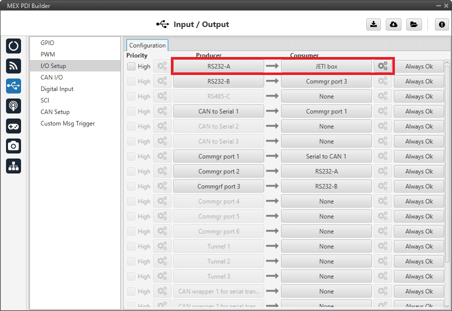
Jetibox Consumer
Configure the Jetibox I/O consumer to retrieve the data. Click on the configuration button (
 icon):
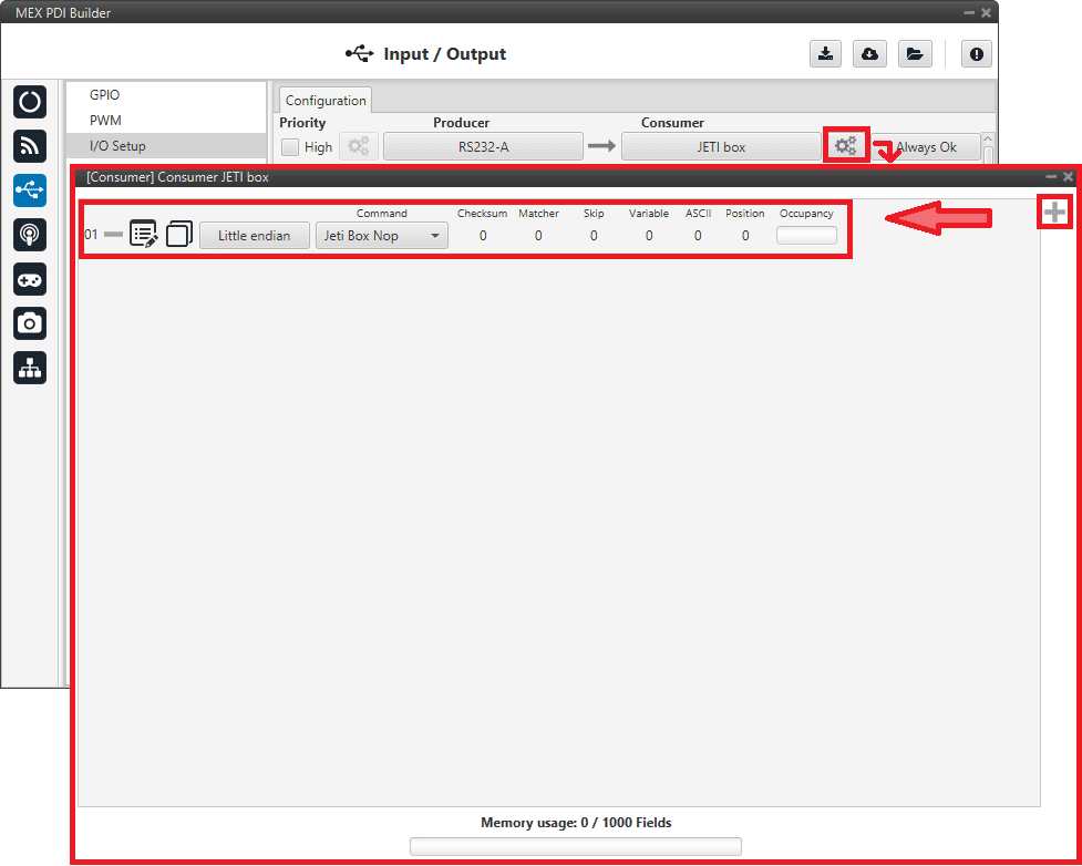
Jetibox Consumer configuration
Below is an example of the custom messages needed to read the Actual Voltage from a Jeti MasterSpin 220 (use Big endian in all messages):
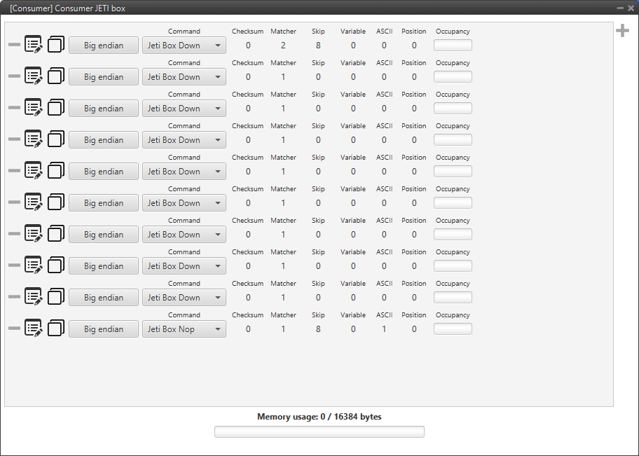
JETI box example
Expected text: “CONTROLLER TYPE MasterSpin 220~”
Command: Jeti box Down
Matcher(32) “CONT” 0x434F4E54 (1129270868)
Skip(24*8) 192
Matcher(32) “220~” 0x3232307E (842150014)
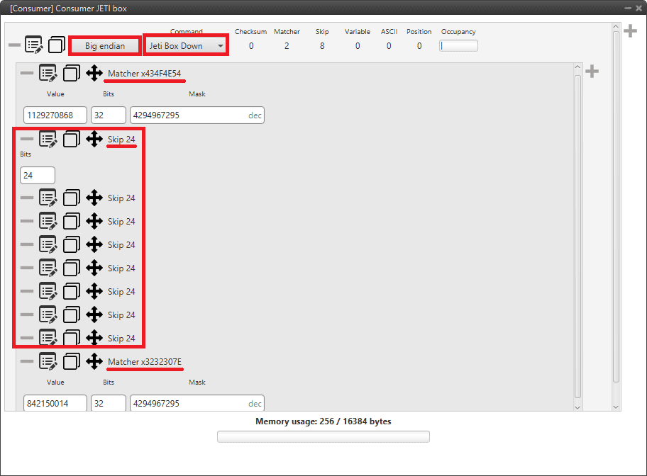
JETI box custom message example
Expected text: “MeasureOrSetting MEASURE ~”
Command: Jeti box Down
Matcher(32) “Meas” 0x4D656173 (1298489715)
Expected text: “Max Temperature”…
Command: Jeti box Down
Matcher(32) “Max ” 0x4D617820 (1298233376)
Expected text: “Min Temperature”…
Command: Jeti box Down
Matcher(32) “Min ” 0x4D696E20 (1298755104)
Expected text: “Actual Temperature”…
Command: Jeti box Down
Matcher(32) “Actu” 0x41637475 (1097036917)
Expected text: “MaxCurrent”…
Command: Jeti box Down
Matcher(32) “MaxC” 0x4D617843 (1298233411)
Expected text: “MinCurrent”…
Command: Jeti box Down
Matcher(32) “MinC” 0x4D696E43 (1298755139)
Expected text: “Max Voltage”…
Command: Jeti box Down
Matcher(32) “Max ” 0x4D617820 (1298233376)
Expected text: “Min Voltage”…
Command: Jeti box Down
Matcher(32) “Min ” 0x4D696E20 (1298755104)
Expected text: “Actual Voltage 11,86 V “
Command: Jeti box Nop
Matcher(32) “Actu” 0x41637475 (1097036917)
Skip(12*8) 96
Parse ascii: int(2), decimal(2), separartor(‘,’)
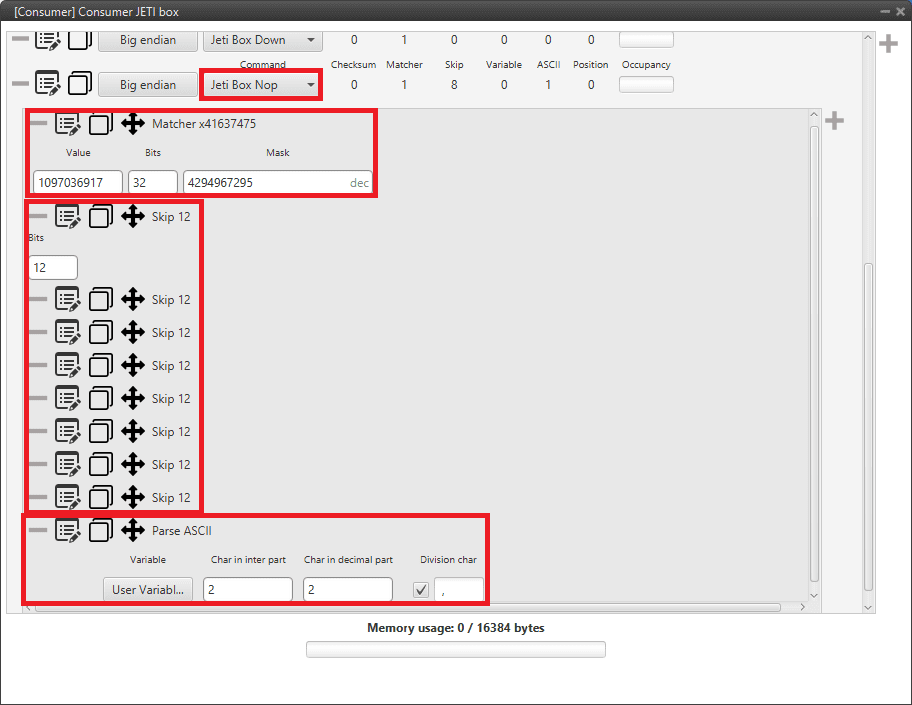
JETI box last custom message example
Reading Arbitration Messages
Note that those messages are generated only if arbitration and messages are enabled in MEX.
Arbiter will send its telemetry in little endian format, using its CAN-TX ID.
The appropriate arbitration message format is described in Arbitration -> CAN Bus protocol section of the MEX Software manual.
Reading/Sending RPMs
This section explains the steps to read RPMs.
MEX PDI Builder side
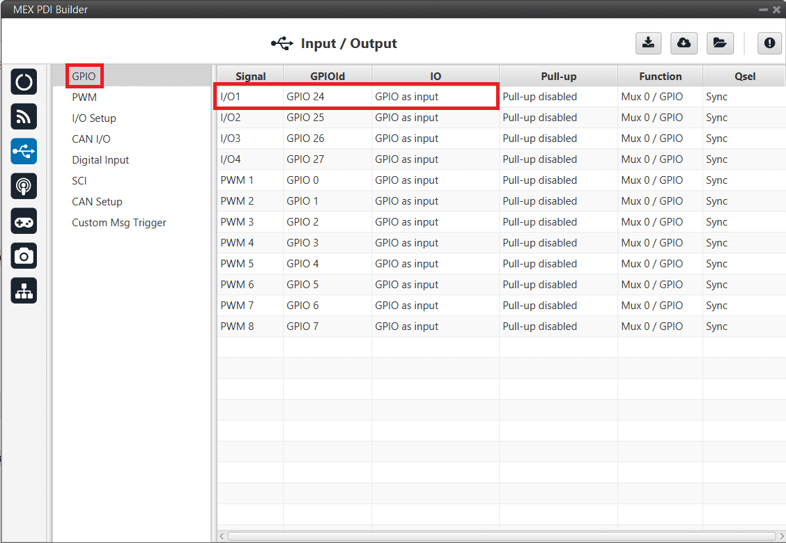
Go to Input/Output menu \(\Rightarrow\) GPIO section.
RPM can be read on the available digital inputs I/O 1-4. The chosen pin needs to be configured as “GPIO as input”. In the example shown here, I/O1 is chosen.
Reading RPMs - GPIO configuration
Go to Input/Output menu \(\Rightarrow\) Digital Input section.
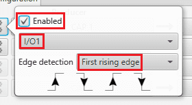
There are 4 possible producers: CAP 1-4. One needs to be chosen and linked to one of the RPMs consumers (RPM 1-4). For more information about Digital input configuration, read the Digital Input section of this manual.
Then, select an edge detection option: “first rising edge” or “first falling edge”.

Reading RPMs - Digital Input
Reading RPMs - Digital Input configuration
Go to Sensors menu \(\Rightarrow\) RPM section \(\Rightarrow\) RPM 1 tab (since RPM 1 has been selected in the Digital Input section).
Here the expected pulse needs to be defined. For more information about RPM configuration, read section RPM of this manual.

Reading RPMs - RPM configuration
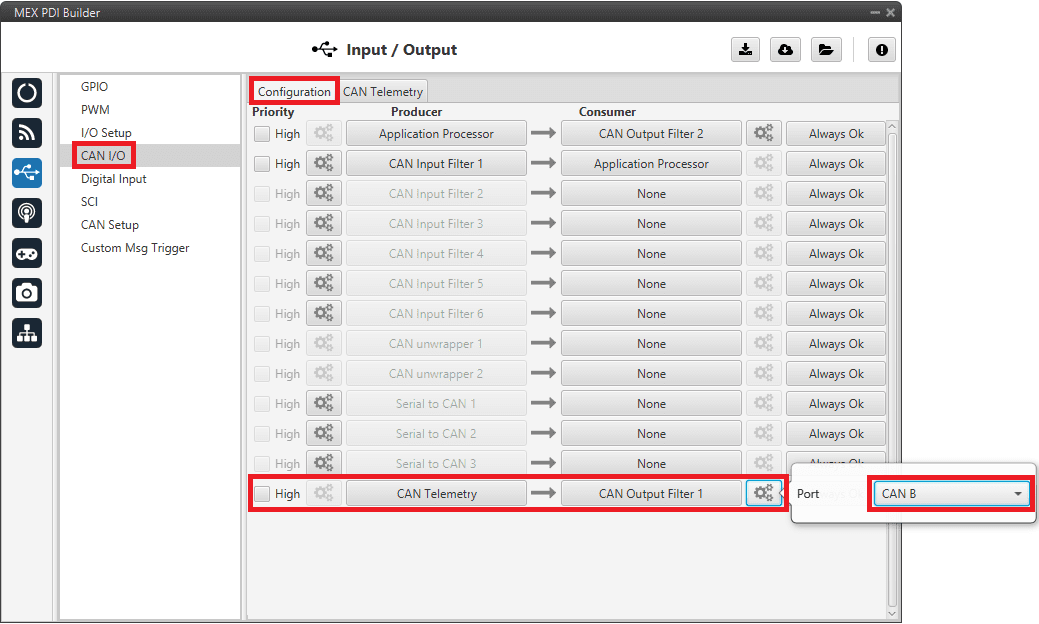
Go to Input/Output menu \(\Rightarrow\) CAN I/O section \(\Rightarrow\) Configuration tab.
Connect CAN Telemetry to a CAN Ouptut Filter as follows (in this example, the RPM1 variable is sent over CAN B bus of the MEX):
Reading RPMs - CAN Custom Telemetry
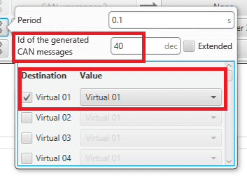
Go to the CAN Telemetry tab.
A new telemetry message needs to be created with its correspondent ID, endianness and period.
Can ID: 1200.
Endianness: Little.
Period: 0.01 s.
In the telemetry message one of MEX variables needs to be selected. As RPM1 has been chosen as consumer in the Digital Input, the variable required to send is RPM1.

Reading RPMs - CAN Custom Telemetry configuration
More information on the configuration of Telemetry messages can be found in the CAN Telemetry section.
1x PDI Builder side
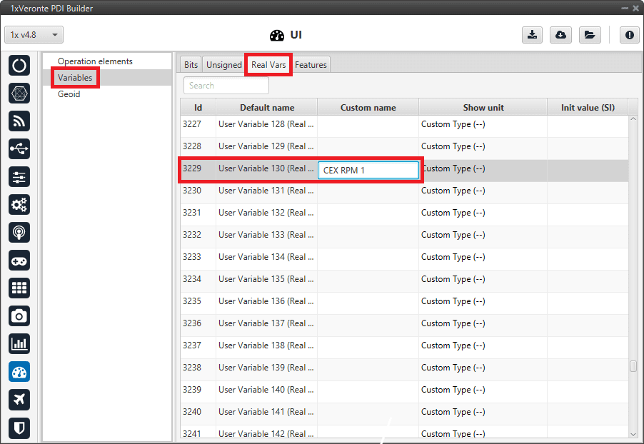
Go to UI menu \(\Rightarrow\) Variables section \(\Rightarrow\) Reals Vars tab.
Rename a Real User Variable (32 bits) that will be used to store the value received from MEX:
1x PDI Builder - User Variable renamed
Go to Input/Output menu \(\Rightarrow\) CAN Setup section \(\Rightarrow\) Mailboxes tab.
Configure some mailboxes to receive the message with ID 1200:

1x PDI Builder - Mailbox configuration
Go to Input/Output menu \(\Rightarrow\) CAN Setup section \(\Rightarrow\) Configuration tab.
Connect an Input filter to a Custom message consumer. Both CAN buses of the autopilot 1x can be used, as well as normal IDs and extended IDs:

1x PDI Builder - Input filter
1x PDI Builder - Input filter configuration
Go to Input/Output menu \(\Rightarrow\) CAN Setup section \(\Rightarrow\) Custom message 1 tab (as Custom Message 1 has been selected as consumer).
Configure the message reading and store the received value in the user variable renamed above:

1x PDI Builder - Custom Message configuration
Scorpion
MEX is able to read telemetry from Tribunus ESCs by connecting it to one of its serial ports. The following steps configure MEX to read this telemetry:
Serial
The user can send information through the serial ports of MEX. For this purpose, please read the following steps:
MEX PDI Builder side
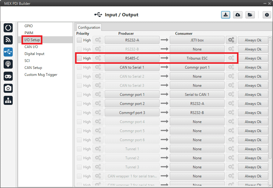
I/O Setup configuration
Reception of serial information on RS232-A (producer) is stored in Serial to CAN 2 (consumer).
Transmission of serial information is sent using the CAN to Serial 2 (producer) through RS232-A (consumer).
(‘Serial to CAN’ and ‘CAN to Serial’ are explained in the I/O section of this manual, click here to access it)
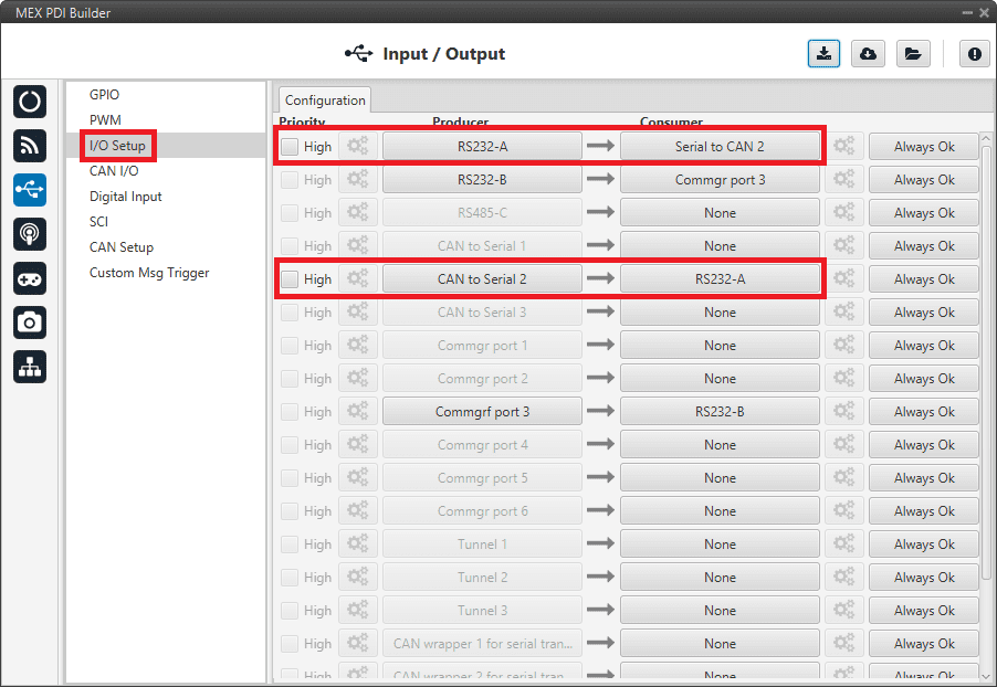
Serial - I/O Setup
CAN I/O configuration
The information that will be sent over serial port RS232-A is going to be received on the MEX over its CAN B port. A mask Id of 51 is added to the Input filter.
The incoming information (from Veronte Autopilot 1x) is processed in ‘CAN to Serial 2’.
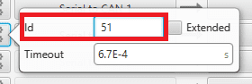
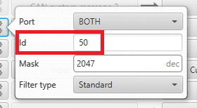
The information coming from port RS232-A and processed as ‘Serial to CAN 2’ is going to be linked to an Output filter.
The information of ‘Serial to CAN 2’ is going to be sent over CAN B with a mask ID of 50 (to be read by Veronte Autopilot 1x).
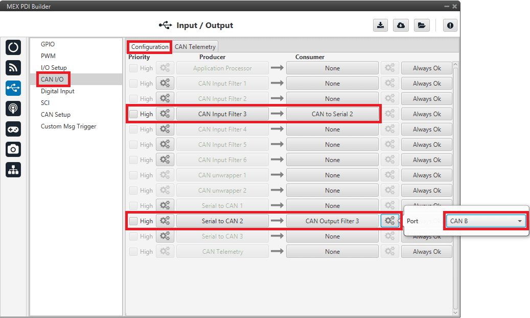
Serial - CAN I/O
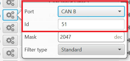
Serial - Input filter configuration

Serial - Serial to CAN configuration
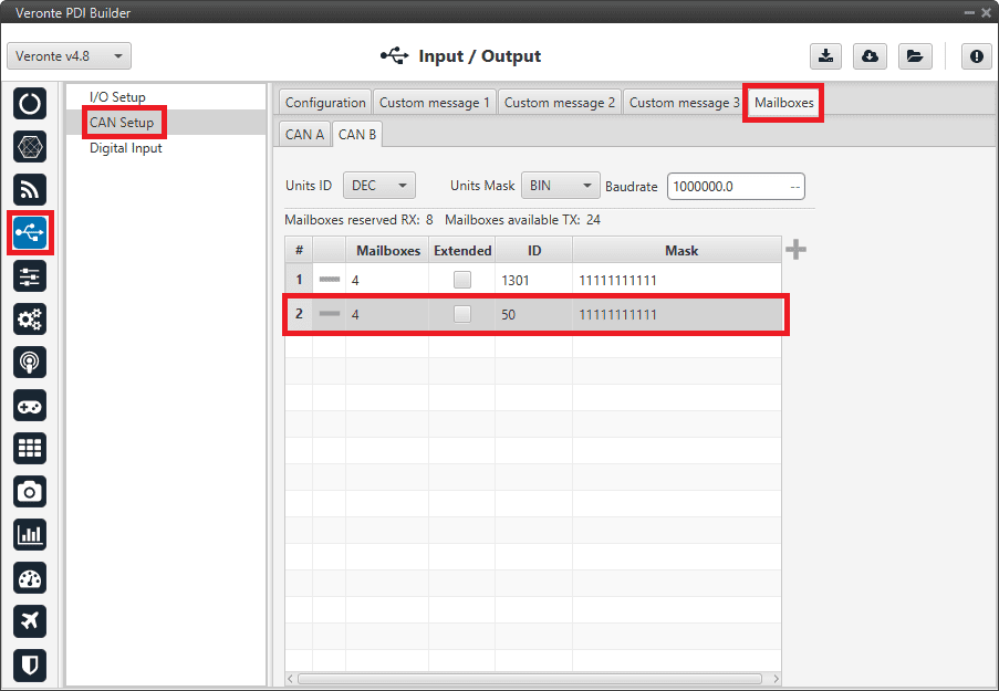
CAN Setup (mailboxes) configuration
Mailboxes need to be defined for the reception of CAN messages. In the example above, mailboxes for ID 51 need to be added on CAN B port.

Serial - CAN Setup configuration
1x PDI Builder side
On the I/O Setup, link an ‘RS Custom Message’ to a ‘Serial to CAN’ with the serial data that autopilot is going to send to MEX.
Then, link a ‘CAN to Serial’ to another ‘RS Custom Message’ with the expected serial messages that MEX will receive in the selected serial port.

Serial - 1x I/O Setup configuration
For the CAN I/O, the same IDs employed in MEX for the Input and Output filters are going to be employed on Veronte Autopilot 1x side, but they must be inverted.
Therefore, the Input filter linked to the chosen ‘CAN to Serial’ needs to have ID 50. And the Output filter linked to the chosen ‘Serial to CAN’ will have ID 51.

Serial - 1x CAN Seup
Serial - 1x Serial to CAN configuration
Serial - 1x Input filter configuration
Some mailboxes with ID 50 have to be created on whichever chosen reception CAN bus.
Serial - 1x Mailboxes configuration
Using MEX as external magnetometer Honeywell HMR2300 for Autopilot 1x
MEX has to be configured with MEX PDI Builder to send the magnetometer measurements by messages, in the same way as Honeywell HMR2300 does. Autopilot 1x also requires a configuration, which is made with 1x PDI Builder.
MEX PDI Builder side
Go to Input/Output menu \(\Rightarrow\) I/O Setup section.
Connect the Custom message producer 1 or 2 to the RS232-A, RS232-B or RS485-C port.

I/O Setup configuration
Click on the
button of the chosen Custom message producer and add a new message (clicking on  ), then configure it as Big endian and set a Period of 0.02 s.
I/O Setup - Custom message configuration
Click on
to add the 3 following Real variables: 313, 314 and 315. Then configure them according to the following table:Parameter
Configuration
Compression
Compress - Bits Signed
Bits
16
Encode
Min: -2.1845334E-4 / Max: 2.1844667E-4
Decode
Min: -32768 / Max: 32767

I/O Setup - Custom message Variables configuration
Click on
\(\Rightarrow\) Matcher to add a matcher to the message and configure it as follows:Parameter
Configuration
Value
13
Bits
8
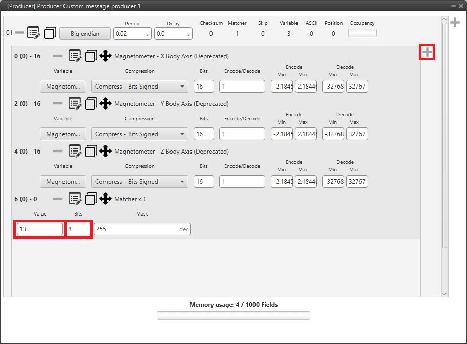
I/O Setup - Custom message Matcher configuration
Warning
The order of variables and matcher must be the same.
Go to SCI menu.
Configure SCI A tab as follows:
Parameter
Configuration
Baudrate
115200
Length
8
Stop
1
Parity
Disabled
Use adress mode
Disabled
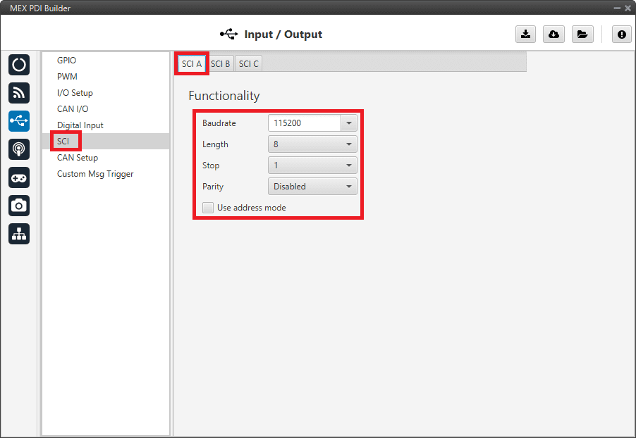
SCI configuration
Once finished the configuration, click on
 to write the configuration in MEX.
Matcher explanation
The matcher is a binary code employed to discard messages with errors.
The length and the number represented can be edited clicking on  of the matcher.
If the receiver does not receive the exact same matcher sequence, the entire message will be discarded, since it will be considered corrupted.
of the matcher.
If the receiver does not receive the exact same matcher sequence, the entire message will be discarded, since it will be considered corrupted.
For more information about custom messages and matchers, read Custom Messages section of the 1x PDI Builder user manual.
1x PDI Builder side
The configuration for the Autopilot 1x is explained in MEX as Magnetometer Honeywell HMR2300 -> Integration examples section of the 1x PDI Builder user manual.
CAN Isolator
MEX can operate as a CAN bus isolator, since it manages both CAN buses as desired. The system has a built-in microcontroller; which manages CAN buses in real-time. Both buses are not electrically connected, in consequence, electrical signals that do not follow the CAN protocol will be isolated.
The functionalities of a CAN isolator are the following:
Filtered CAN subnet
With MEX it is possible to filter certain messages from one CAN line (Line A) and transmit specific information through the other one (Line B). This is a specific case of CAN input filter.
The following diagram summarizes an application example to filter a CAN subnet:
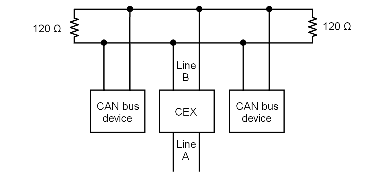
Sub CAN example diagram
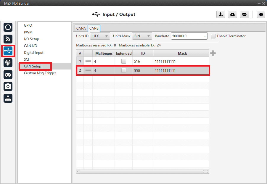
In this example, only a certain range of CAN IDs will be allowed to cross from Line B to Line A. The allowed range will be from 0x550 to 0x55F.
Create a new mailbox entry for Line B. Assign some of the mailboxes to it and set the ID to 0x550.
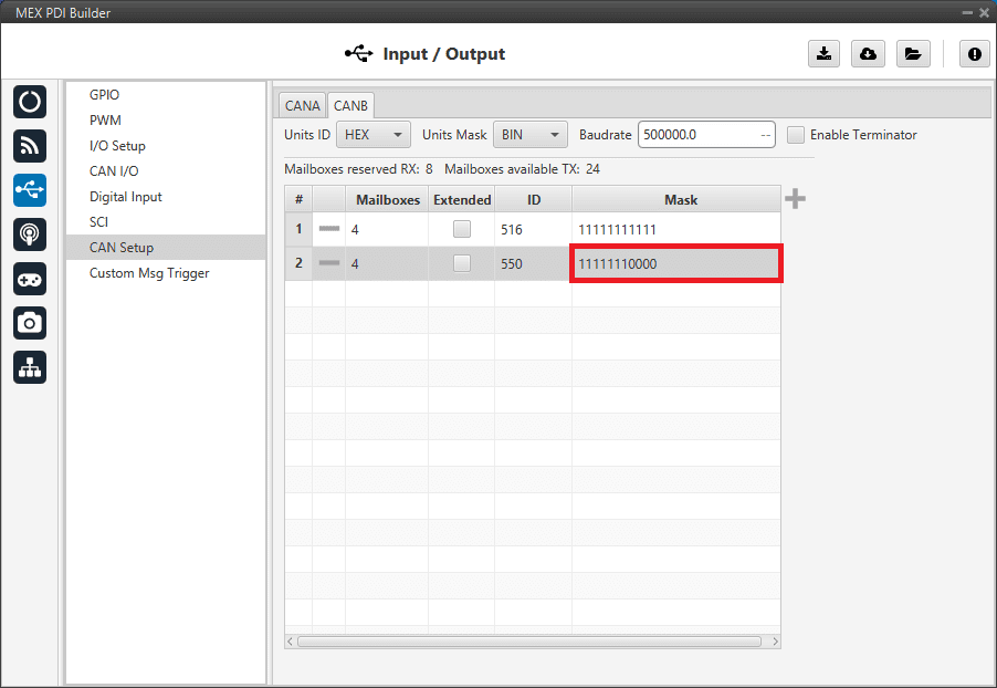
Set a Mask which will ignore the last 4 bits.
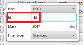
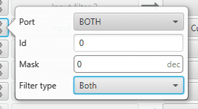
Configure CAN Input Filter 2 on CAN B, with the same settings as the Mailbox.
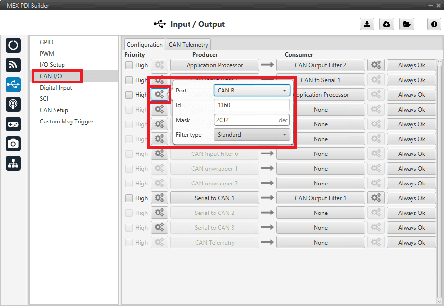
Important
This menu only allows decimal numbers. For this example the Id 0x550, is represented as 0d1360.
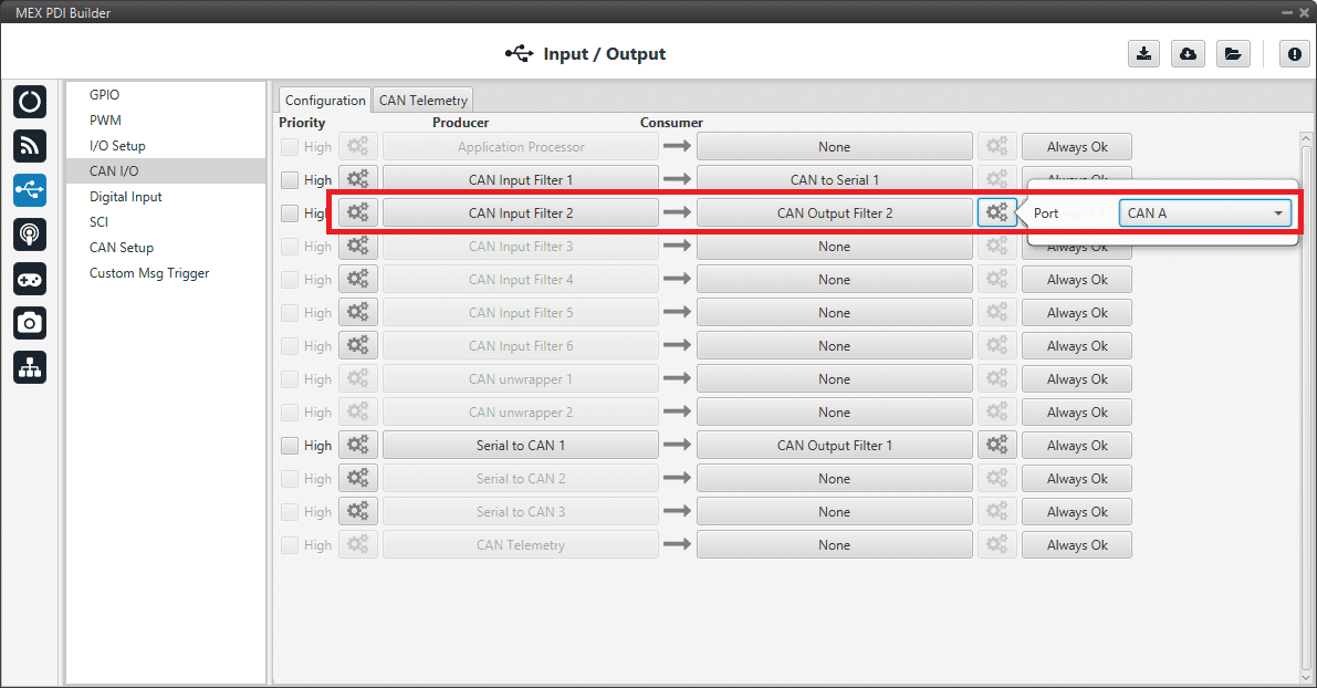
Bind CAN Output Filter 2 to CAN Input Filter 2, configured to CAN A.
CAN tunnel
A CAN tunnel is a specific case of messages tunnel. The electrical diagram is very similar to Filtered CAN subnet.
In this example, a transparent tunnel will be created. So, any messages received on Interface A will be sent through Interface B. Optionally, the mailboxes can be equally distributed to support both standard and extended CAN IDs.
Create a new mailbox entry for Interface A. Assign half of the mailboxes to it and set a Mask of 0.
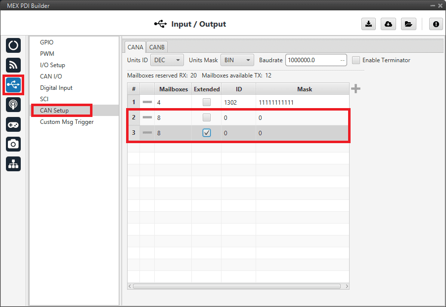
Configure CAN Input Filter 2 on CAN A, with a Mask of 0 and Both types.
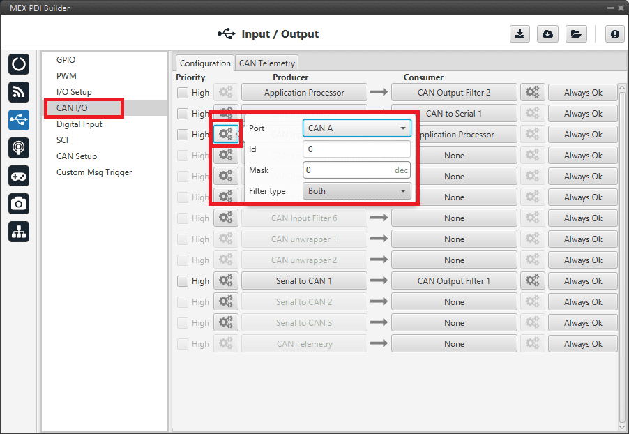
Bind CAN Output Filter 2 to CAN Input Filter 2, configured to CAN B.
